How to design and manufacture a high precision optical lens mold?
Inquiry- Description
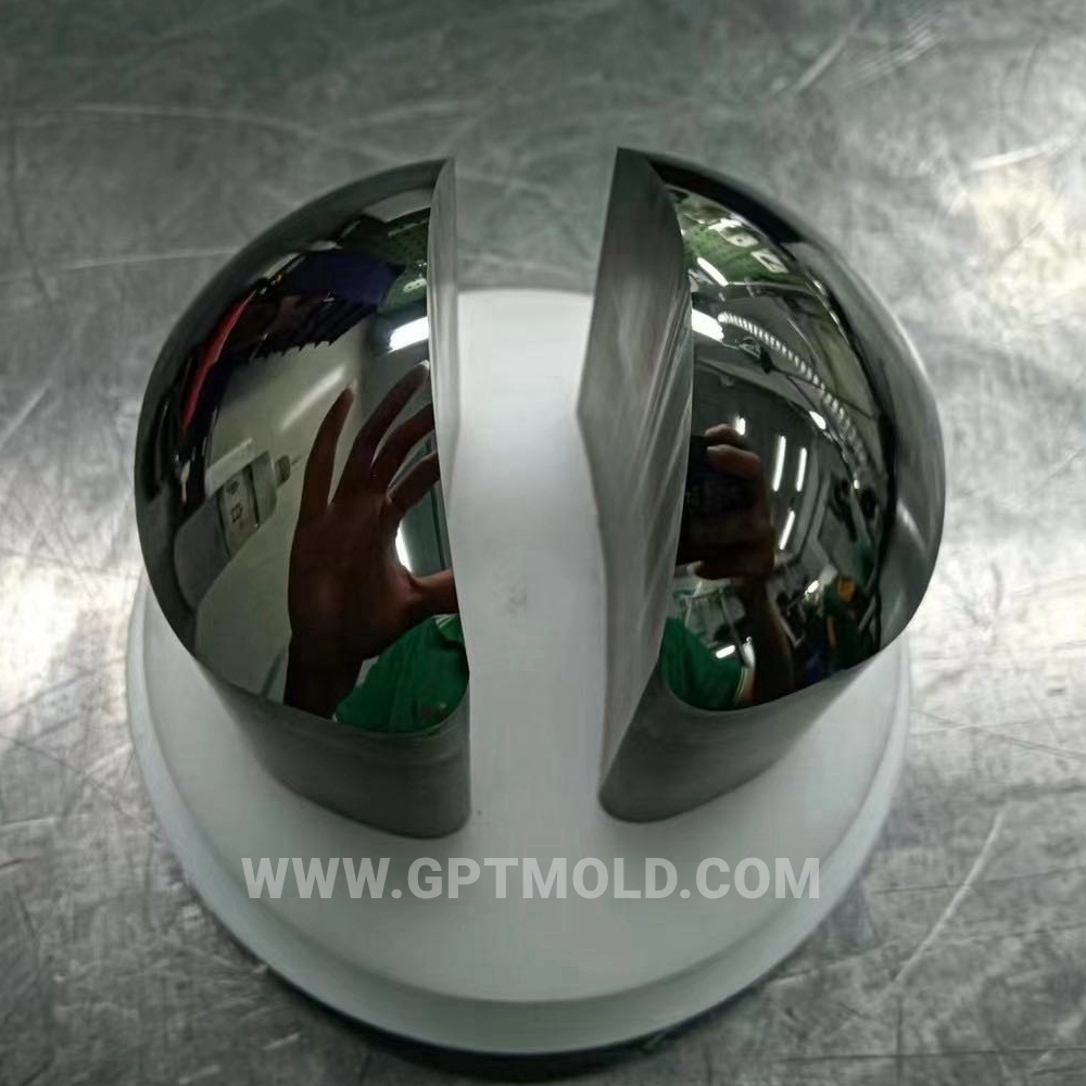
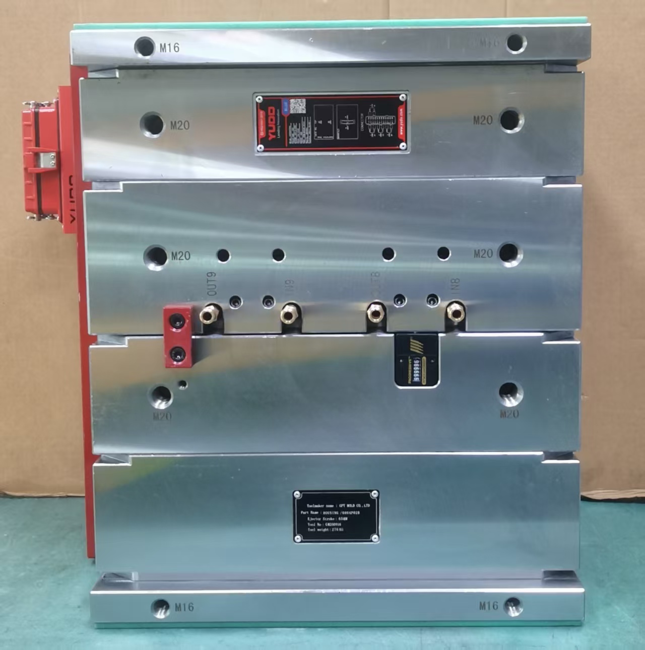
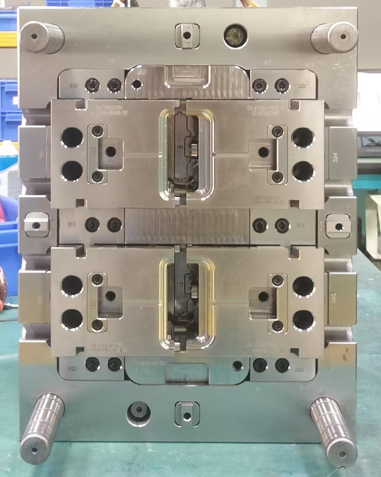
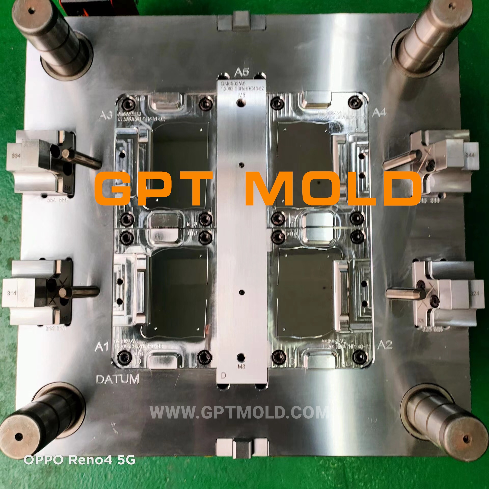
optical lens mold inserts
Designing and manufacturing a high-precision optical lens mold demands ultra-strict control over material selection, structural design, machining processes, and surface treatment, as it directly determines the optical performance (e.g., transmittance, imaging accuracy) of the molded lenses. Below is a systematic, step-by-step guide to the design principles and manufacturing processes for such molds, tailored to the requirements of optical components like non-spherical lenses, LED optical lenses, and camera lenses:
Design & Manufacture of High-Precision Optical Lens Molds
- Core Design Principles for Optical Lens Molds
1.1 Material Selection: Balance Hardness, Corrosion Resistance, and Thermal Stability
The mold material must meet nanoscale surface finish requirements and maintain dimensional stability under repeated thermal cycles. Key material choices and their applications are as follows:
Base Mold Material: Use S136/STAVAX stainless steel (hardness ≥55 HRC after vacuum quenching) for mold cavities and cores. It offers excellent corrosion resistance and polishability, ideal for PC/PMMA optical lens molds.
Micro-Structure Inserts: For non-spherical or micro-patterned lens molds, adopt tungsten carbide or nickel-phosphorus alloy plating (electroplated nickel layer with thickness 2–4μm). Nickel layers are soft and easy to machine with diamond tools, reducing tool wear and achieving Ra ≤0.01μm surface finish.
High-Temperature Applications: For high-temperature resin lenses (e.g., COP), use maraging steel (HRC50–55) with a low thermal expansion coefficient (11×10⁻⁶/℃) to minimize thermal deformation.
1.2 Structural Design: Ensure Concentricity and Precision Alignment
Optical lens molds require micron-level concentricity (≤0.003mm) to avoid lens eccentricity and imaging distortion. Key structural design measures include:
Precision Locating Mechanism: Add 4 pairs of tapered precision positioning pins (interference fit: pin diameter 0.001–0.003mm larger than the hole) to the mold plate. Heat the mold plate to 70°C for assembly, ensuring zero clearance and eliminating alignment errors caused by guide pillar gaps.
Core-Cavity Fit Control: Design the core with a two-stage fit: the small end (main fit) has a clearance of 0.002–0.003mm (stationary mold) or 0.003–0.005mm (moving mold) to guarantee concentricity; the large end has an enlarged clearance of 0.008–0.015mm to avoid secondary clamping errors.
Cooling System Optimization: Integrate micro-conformal cooling channels (3D-printed or laser-drilled) around the core to control mold temperature variation ≤±3°C. This reduces thermal warpage of the lens and ensures uniform solidification of the resin.
1.3 Gating and Venting Design: Minimize Residual Stress
Gate Design: Use pin-point gates or edge gates (diameter 0.5–1mm) for small optical lenses to avoid flow marks on the optical surface. For large non-spherical lenses, adopt a hot-runner system with multi-zone temperature control (nozzle temperature variation ≤±3°C) to ensure balanced filling.
Micro-Venting Design: Add micro-vent slots (width 0.05–0.1mm, depth ≤0.03mm) at the cavity’s last filling position to exhaust trapped gas. Use vent inserts for easy replacement and prevent blockage during production.
- Step-by-Step Manufacturing Process
2.1 Pre-Processing: Material Preparation and Stress Relief
Material Forging and Conditioning: Forge S136 steel to uniform grain structure, then perform quenching and tempering to reach 30–36 HRC for rough machining.
Rough Machining: Use CNC milling to shape the mold blank, leaving a 0.3mm machining allowance for cavities and cores. Perform stress relief annealing (600–650°C) after roughing to eliminate machining-induced stress.
Heat Treatment: Conduct vacuum quenching + tempering on the mold plate to achieve 55 HRC hardness. This step ensures wear resistance and dimensional stability.
2.2 Precision Machining: Nanoscale Accuracy Control
Semi-Finishing: Use surface grinding to ensure the mold plate’s flatness ≤0.002mm and perpendicularity ≤0.01mm. Use wire EDM to machine locating holes and core holes, leaving a 0.03mm finish allowance.
Ultra-Precision Machining:
Moore Jig Grinder Processing: Machine cavities, core holes, and locating holes in one clamping to ensure concentricity ≤0.001mm. This is critical for multi-cavity lens molds to guarantee consistent lens quality.
Diamond Turning: For non-spherical lens surfaces, use a diamond tool lathe to machine the electroplated nickel layer (cutting depth 2–4μm), achieving Ra ≤0.01μm surface finish and parallelism 0.1–0.2μm.
In-Process Inspection: Use a coordinate measuring machine (CMM, accuracy ±0.001mm) to inspect cavity dimensions, concentricity, and surface roughness after each machining step.
2.3 Surface Treatment: Mirror Polishing and Anti-Adhesion Coating
Mirror Polishing: Polish the cavity surface with diamond paste (particle size from 6μm to 0.25μm) to reach SPI A-1 grade (Ra ≤0.005μm) for high-transmittance lenses like camera lenses.
Protective Coating: Apply DLC (diamond-like carbon) or TiN coating (thickness 2–5μm) to the core surface. This reduces friction between the mold and resin (e.g., PMMA/PC), preventing lens sticking and extending mold life.
2.4 Assembly and Testing: System-Level Validation
Mold Assembly: Assemble the mold with precision lubricants (high-temperature resistant, low-oil) on core fit surfaces. Calibrate the clamping force to ensure uniform pressure (variation ≤±2%) and avoid cavity deformation.
Trial Molding and Validation:
Conduct trial injection with optical-grade resin (e.g., PMMA CR-39) and test lens performance: check transmittance (≥90%), surface defects (no flow marks/burn marks), and concentricity (≤0.003mm).
Use optical profilometry to inspect the lens surface topography and validate the mold’s replication accuracy of micro-structures (e.g., optical gratings).
- Key Quality Control Points
Thermal Stability: Monitor mold temperature in real time with thermocouples to ensure variation ≤±3°C during production.
Cleanliness Control: Process the mold in a Class 1000 cleanroom to prevent dust contamination on the optical surface.
Preventive Maintenance: Clean the hot-runner nozzles and micro-vents every 50,000 cycles with ultrasonic cleaning to avoid blockage and gas traps.
Category With Sidebar Optical mold