- Overmolding Tooling
- SMC BMC Mold
- Engineering & Services-
- Die Casting Mold
- Project Showcase
- Gas Assist Injection
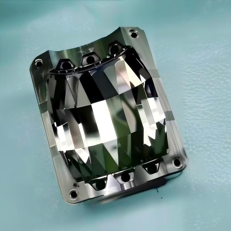
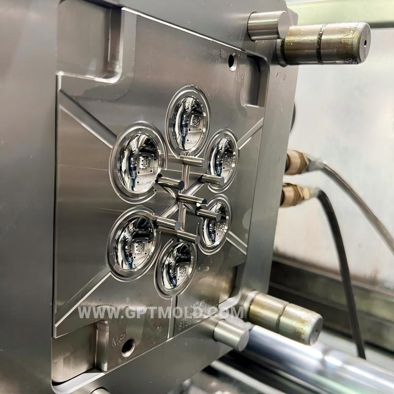
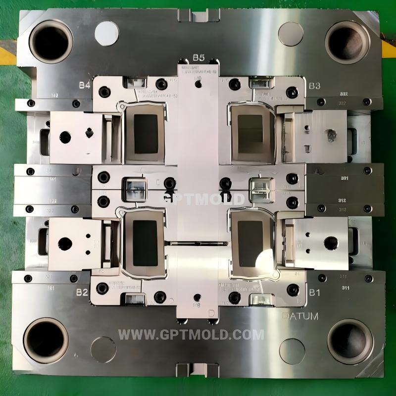
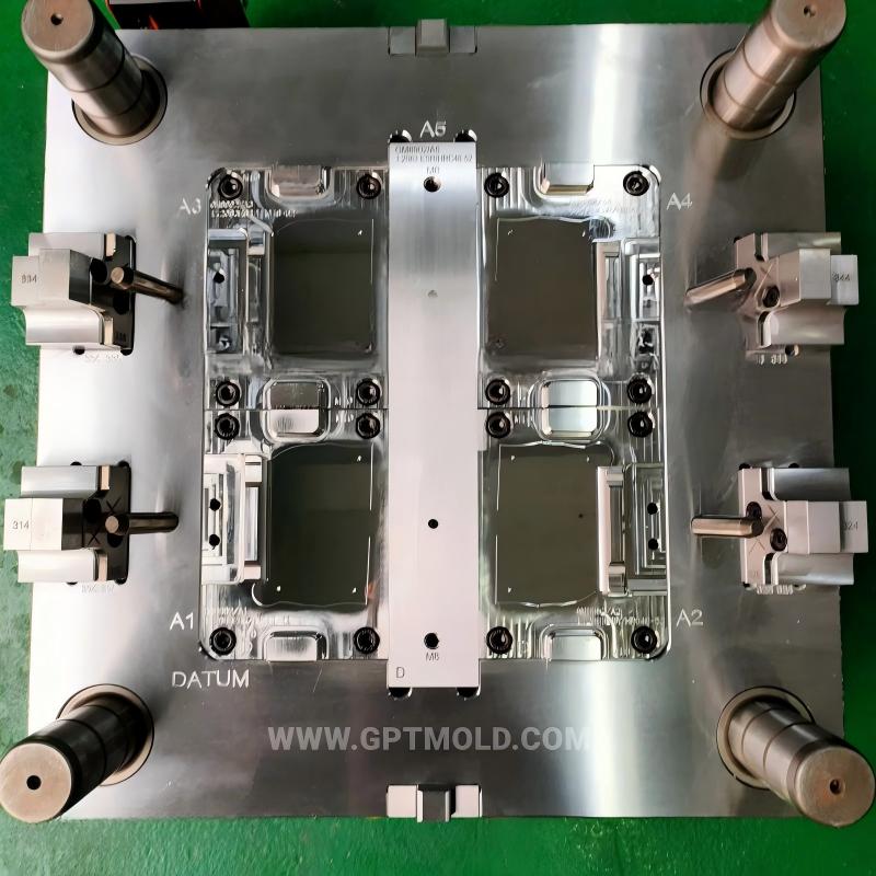
- Optical Lens Molds
- Silicon Rubber
- Two-Shot Injection Molds
- Auto inspection fixtures
- High Precision Electronic Molds
- Quick Mold Prototyping
- Unscrew Molds
- Insert Molding
- Ultra Precision Component Tooling
- Surface Treatment Finishing
- Automotive Moulds
- Lighting & Optics
- Medical & Healthcare
- Electronics Mould Tooling
- Automotive Lighting Parts
- Medical Device Components
- Consumer Electronics
- Capabilities
- Industrial Applications
- Category With Sidebar
- Category with no image
- Category 3 column
- Category 2 Column
- Category With List Style
- Category With No Sidebar
High-Precision Optical Lens Mold Manufacturing Quality Checklist
Inquiry- Description
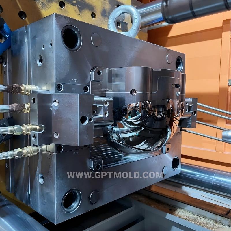 checklist applies to the production of molds for optical lenses (e.g., camera lenses, LED optical lenses, non-spherical lenses) with precision requirements of concentricity ≤0.003mm and surface roughness Ra ≤0.005μm. It covers 5 core stages: material preparation, precision machining, surface treatment, mold assembly, and trial validation, with clear acceptance criteria and inspection methods for each item.
| Stage | Check Item | Technical Requirement | Inspection Method | Acceptance Standard | Responsible Party | Remarks |
| 1. Material Preparation & Pre-Processing | 1.1 Mold blank material certification (cavity/core) | Material: S136/STAVAX stainless steel; chemical composition compliance with ASTM standard; for COP high-temperature lenses, use maraging steel (18Ni-300) | Review material certificate + spectral analysis | Certificate matches batch number; chemical composition deviation ≤±0.05% of standard value | Material QC Team | Vacuum degassing required for maraging steel to eliminate internal pores |
| 1.2 Forging and stress relief annealing (rough machining stage) | Forging grain flow direction consistent with cavity contour; stress relief annealing at 600–650°C for 4–6h, cooling rate ≤50°C/h | Metallographic inspection + hardness testing | Grain uniformity ≥Grade 2; surface hardness after annealing: 30–36 HRC | Heat Treatment Team | Avoid rapid cooling to prevent new stress | |
| 1.3 Vacuum quenching & tempering (final heat treatment) | Vacuum quenching at 1020–1050°C, 3× tempering at 500–520°C; hardness target: 55–58 HRC (S136) / 50–55 HRC (maraging steel) | Rockwell hardness tester (3 points per component) + ultrasonic flaw detection | Hardness variation ≤±1 HRC; no internal cracks or inclusions (flaw size ≤0.01mm) | Heat Treatment Team | Tempering time extended by 1h for large mold cores to ensure hardness uniformity | |
| 2. Precision Machining | 2.1 Mold plate flatness and perpendicularity (semi-finishing) | Flatness ≤0.002mm/100mm; perpendicularity between mold plate surface and guide pillar holes ≤0.01mm | Precision surface grinder + laser interferometer | Full-area measurement, maximum deviation ≤0.0015mm | CNC Machining Team | One-side grinding to avoid repeated clamping errors |
| 2.2 Locating pin hole machining (wire EDM) | Hole diameter tolerance: ±0.001mm; concentricity between paired holes ≤0.002mm | CMM (coordinate measuring machine, accuracy ±0.001mm) | 100% inspection of all 8 locating holes, no out-of-tolerance items | EDM Team | Machining completed in one clamping to ensure positional accuracy | |
| 2.3 Cavity/core semi-finishing (Moore jig grinder) | Machining allowance: 0.03mm for cavity surface; concentricity of core hole ≤0.001mm | CMM + optical comparator | Concentricity deviation ≤0.0008mm; allowance uniform (variation ≤0.005mm) | Precision Grinding Team | Jig grinder spindle runout ≤0.0005mm during processing | |
| 2.4 Ultra-precision diamond turning (non-spherical surface) | Cutting depth: 2–4μm (nickel-phosphorus plating layer); surface roughness target: Ra ≤0.01μm; non-spherical surface profile error ≤0.5μm | Optical profilometer + diamond tool wear monitor | Profile deviation ≤0.3μm; Ra ≤0.008μm; tool wear ≤0.001mm per 10 components | Ultra-Precision Machining Team | Processed in Class 1000 cleanroom to avoid dust scratches | |
| 3. Surface Treatment | 3.1 Mirror polishing (cavity/core surface) | Polishing sequence: 6μm→3μm→1μm→0.25μm diamond paste; target grade: SPI A-1 (Ra ≤0.005μm) | Atomic force microscope (AFM) + visual inspection (10× magnifying glass) | No scratches, pits or orange peel; Ra ≤0.004μm; surface flatness ≤0.001mm | Polishing Team | Final polishing with colloidal silica to improve surface gloss |
| 3.2 DLC/TiN coating (core surface) | Coating thickness: 2–5μm; adhesion strength ≥50N (pull-off test); friction coefficient ≤0.15 | Coating thickness gauge + pull-off adhesion tester | Thickness variation ≤±0.5μm; no coating peeling or bubbling | Surface Treatment Team | Coating applied after final polishing to avoid damage | |
| 3.3 Nickel-phosphorus plating (micro-structured inserts) | Plating thickness: 2–4μm; plating uniformity ≤±0.2μm; surface hardness: 50–55 HRC | Eddy current thickness gauge + micro-hardness tester | Uniformity meets requirement; no plating voids on micro-patterns | Plating Team | Plating pre-treatment includes degreasing and activation to ensure adhesion | |
| 4. Mold Assembly | 4.1 Precision locating pin assembly | Interference fit: pin diameter 0.001–0.003mm larger than hole; mold plate heated to 70°C for press-fitting | Torque wrench + CMM (post-assembly inspection) | No pin looseness; concentricity of mold plate after assembly ≤0.003mm | Assembly Team | Use heat-resistant lubricant during press-fitting to avoid pin jamming |
| 4.2 Core-cavity fit adjustment | Main fit clearance (small end): 0.002–0.003mm (stationary mold); 0.003–0.005mm (moving mold); auxiliary fit clearance (large end): 0.008–0.015mm | Feeler gauge + CMM (coaxiality measurement) | Clearance within range; coaxiality of core and cavity ≤0.002mm | Assembly Team | Test fit with dummy core before formal assembly | |
| 4.3 Cooling circuit integrity test | Pressure test at 1.5× working pressure (1.5MPa); holding time 30min | Pressure gauge + bubble leak detector | No pressure drop (≤0.01MPa/30min); no water leakage at joints | Hydraulic Test Team | Conformal cooling channels to be inspected via industrial CT for blockage | |
| 4.4 Hot-runner system calibration (for large lenses) | Nozzle temperature variation ≤±3°C; temperature response time ≤10s | Temperature data logger (3 thermocouples per nozzle) | Temperature stability meets requirement; no nozzle clogging | Hot-Runner Team | Preheat for 30min before calibration to reach thermal equilibrium | |
| 5. Trial Molding & Performance Validation | 5.1 Trial resin material (optical grade) | Material: PMMA CR-39/PC LEXAN 141R/COP; purity ≥99.9%; no particulate impurities (≥0.1mm) | Material certificate + particle counter test | Impurity count ≤5 particles/kg; resin transmittance ≥92% | Injection Team | Resin dried for 4–6h at 80–100°C before molding |
| 5.2 Mold temperature stability during trial | Mold temperature variation ≤±3°C; cooling water flow rate: 5–8L/min per channel | Real-time thermocouple monitoring (4 points around cavity) | Temperature fluctuation ≤±2°C; flow rate stable (variation ≤±0.5L/min) | Process Control Team | Use constant temperature water chiller for precise control | |
| 5.3 Molded lens dimensional inspection | Concentricity ≤0.003mm; thickness variation ≤0.005mm; non-spherical profile error ≤0.5μm | Optical CMM + lens centering tester | All dimensions within tolerance; no eccentricity-induced astigmatism | Quality Inspection Team | Sample size: 20 lenses per batch, 0 acceptance for out-of-tolerance | |
| 5.4 Lens optical performance test | Light transmittance ≥90%; no flow marks/burn marks (visual inspection under 20× magnification); surface defect size ≤0.01mm | Spectrophotometer + optical microscope | Transmittance ≥91%; no visible defects; surface scratch count ≤0 per lens | Optical Lab Team | Test in darkroom to avoid ambient light interference | |
| 5.5 Mold durability test (accelerated) | 10,000 injection cycles; cavity surface wear ≤0.001mm; coating adhesion remains ≥45N | AFM (post-test surface inspection) + adhesion test | Wear within limit; no coating peeling; lens quality consistent (defect rate ≤0.5%) | Reliability Test Team | Maintenance (ultrasonic cleaning) after 5,000 cycles to remove residue |
Category With Sidebar Optical mold