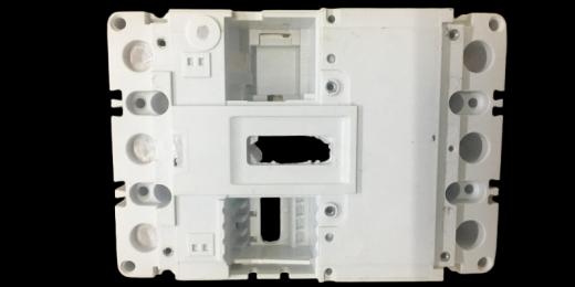
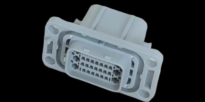
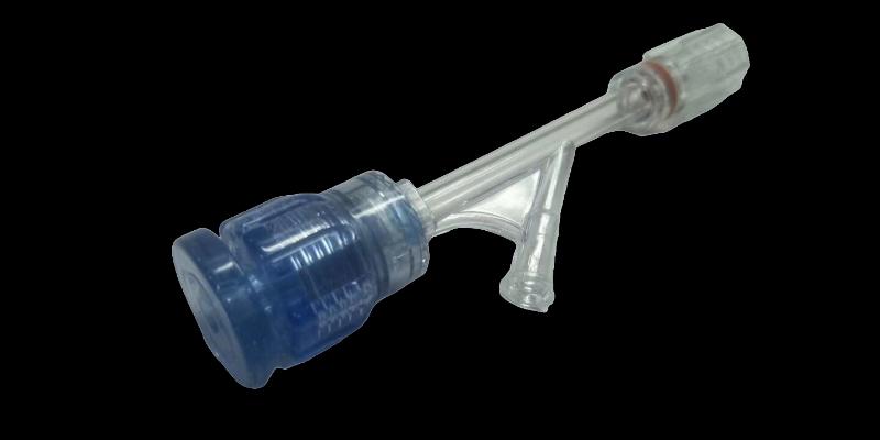
A texture plaque can show a preferred pattern, but it cannot show how that pattern will release from every wall of a molded housing. A narrow recess, a sliding feature and a broad external face may all require different attention even when the drawing assigns them the same texture.
A mold texture and draft review is most useful before final finishing, while geometry and tooling decisions can still be coordinated. Its purpose is to close the details that a texture number alone leaves open.
Make a surface map that the toolmaker can use
Assign the texture reference and appearance requirements to named surfaces on the current part model. Mark boundaries against polished regions, sealing faces, lettering, datum features and interfaces with mating parts. Show which surfaces are visible after assembly.
Where a texture changes direction around a corner or crosses a tooling junction, specify the intended visual relationship. A directional grain may look acceptable on one panel yet appear inconsistent when the adjoining panel is installed. Review the assembled product, not only the isolated CAD part.
Include this map in the DFM review. It gives the mold designer a concrete basis for discussing draft, parting lines and the location of surface transitions.
Evaluate draft in the actual release direction
Draft is relevant to the direction in which the part separates from the surface forming it. Review each textured region against its local tooling action, including slides and lifters where present. A color-coded analysis referenced only to the main mold-opening direction may not answer the question for a side-action feature.
Standex Engraving Mold-Tech identifies part geometry, material, texture construction and molding conditions as factors affecting release. Its technical guidance also treats different tooling actions and shrink-on conditions separately. This supports a feature-specific review rather than reliance on a single draft rule for the entire component. Mold-Tech technical texture guidance.
Ask the selected texture specialist and toolmaker to assess the actual design. Record any proposed local adjustment and its appearance consequence. Do not quietly reduce texture depth in a difficult area without confirming that the resulting visual transition is acceptable.
Confirm the boundaries that protect function
Consider a housing with a textured outside wall and a narrow sealing land along its rim. The texture boundary needs a defined position because the seal and the visible wall serve different purposes. A broad note to “texture all external surfaces” could leave that decision unresolved.
Mark protected areas using the supplier’s agreed drawing and masking conventions. Include edges that will contact fixtures or inspection datums, where the surface condition affects how the part is located. Confirm the treatment of small lettering and logos so that the intended detail remains legible.
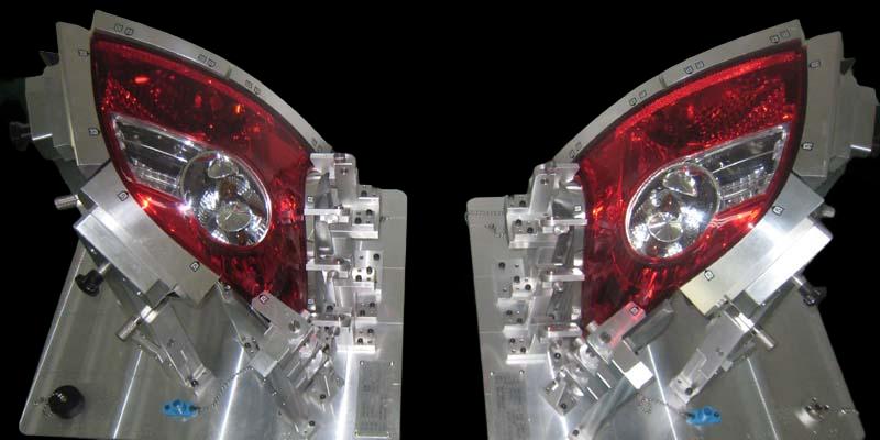
If several cavity inserts form a continuous visible surface, agree how the texture and boundary information will be controlled across them. The approval should cover the assembled result, not only individual tool components viewed separately.
Decide when the tool is ready for texturing
Review open dimensional corrections, unresolved release concerns and any likely changes to the visible surface before authorizing final finishing. Completing texture before these matters are settled can add unnecessary work when a later modification reaches the same area.
Ask the toolmaker and texture supplier to confirm surface preparation and disclose relevant repairs or material differences in the areas to be treated. The agreed preparation should follow the specialist’s requirements for the chosen process rather than an assumption that every polished cavity is ready for the same treatment.
Record what has been approved at this stage. Approval to texture the tool is a manufacturing release; it need not imply that the final molded appearance has already been accepted.
Judge production-representative parts
After texturing, evaluate parts made with the specified material and color under documented trial conditions. Check appearance and clean release, including scuffs or drag marks in difficult areas. Compare matching components together when the product depends on a consistent assembled appearance.
Use identified samples and agreed viewing conditions. A reference plaque is useful for communicating design intent, while the molded component demonstrates the result on its actual geometry. Keep both references clearly labeled so they are not used interchangeably.
Close the review through the mold-validation process with the final surface map, approved samples and any remaining restrictions. This makes future cavity repairs or product revisions easier to assess without reconstructing which boundaries and release conditions were originally accepted.