

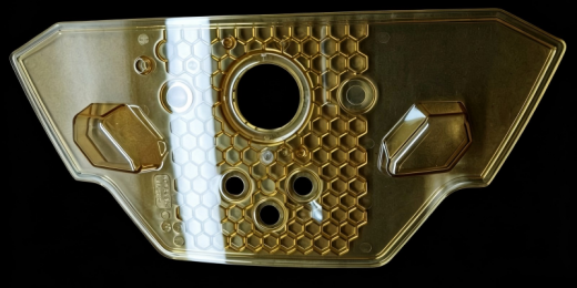
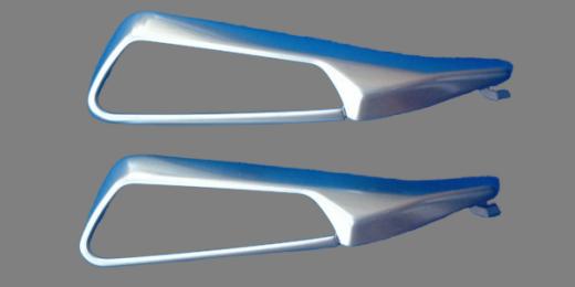
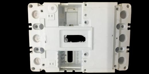
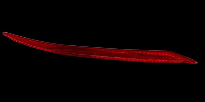
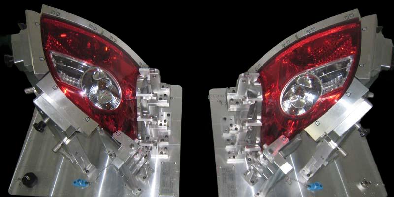
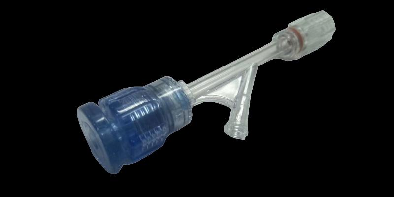
This technical study reviews archived filling-analysis slides for left- and right-hand rear-housing components. It focuses on the report's weld-line and end-of-flow venting observations, with proposed tooling-review checkpoints rather than a production-outcome claim.
Establish the common study conditions
The archive identifies ABS PA-765A, a mold-temperature input of 50°C and a melt-temperature input of 250°C. These are recorded simulation conditions. Their relevance to a new project would depend on the actual resin specification, part revision, mold arrangement and intended processing window.
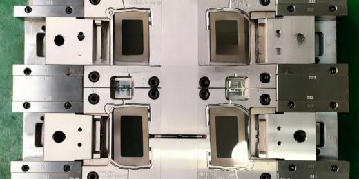
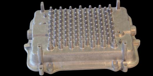
Left- and right-hand labels make a controlled comparison especially important. The review should first establish which geometry belongs to each report and how the gate, runner and mold references are represented. It should then confirm that the plots being compared come from the intended study revision.
That preparation gives an engineering discussion a reliable starting point. A visually similar plot is not sufficient if the geometry, material data or analysis setup has changed between runs.
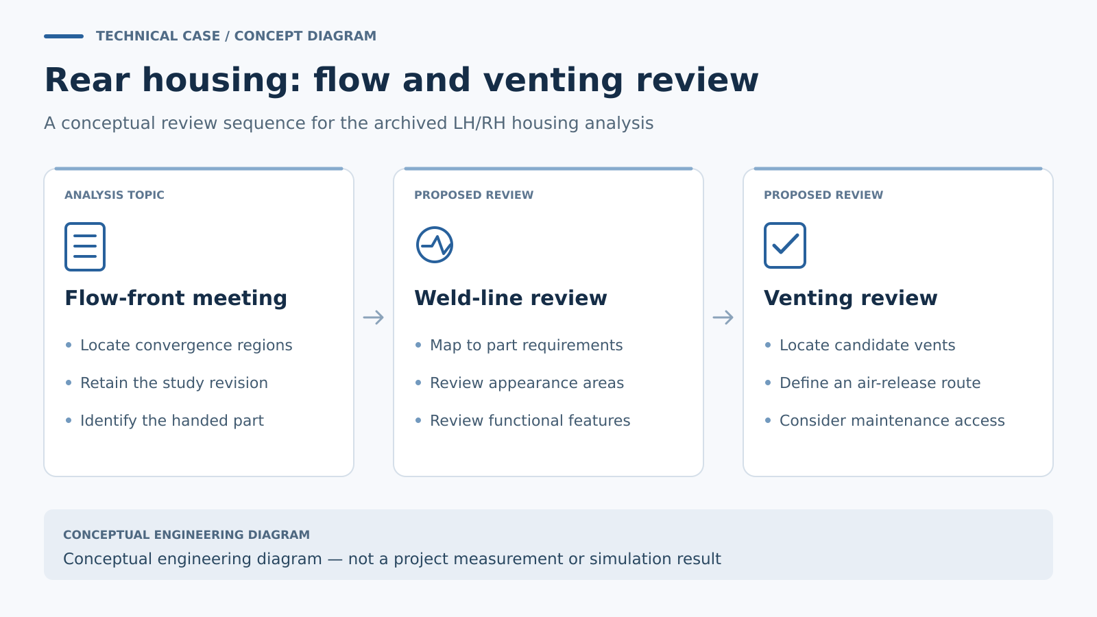
Connect a weld-line prediction to a part requirement
The archived report highlights weld-line locations and recommends attention to venting. To turn that observation into a tooling decision, the next step would be to place each predicted convergence region on the current part drawing.
A reviewer can then ask whether the location intersects a specified appearance area, assembly feature or load-bearing region. The answer should come from the part requirements. The archive does not establish that a visible line caused a field failure or that any particular feature had a structural problem.
As general analysis guidance, Autodesk recommends reviewing how flow fronts converge and considering weld-line position together with processing conditions. Gate or thickness changes can move a convergence location, but any proposed change also needs to respect the part's functional constraints. Technical reference: Autodesk weld-line troubleshooting.
Turn end-of-flow observations into a vent review
A predicted late-filling region needs a practical discussion of where air can leave the cavity. For the rear housing, the report's recommendation provides the reason to inspect the relevant edge and tooling surfaces in the mold design.
The vent proposal should identify the actual cavity location, available route to atmosphere and how that route can be maintained. Any vent dimensions must be chosen for the resin and tool conditions; a generic depth copied from another project would be an incomplete design basis.
It is also worth distinguishing an air-trap indication from a fully defined venting analysis. If a detailed air-pressure result is required, the analysis setup needs to represent the intended vent conditions. Autodesk describes using vent-region pressure together with air-trap results when evaluating possible vent locations. Technical reference: vent-region pressure.
Carry a location-based plan into the trial
A useful trial plan would preserve the same location references used in the simulation review. It could compare the observed fill progression and surface condition with the selected report, while recording the machine settings and material preparation for each sample set.
For paired parts, the samples and records should remain identifiable as left-hand or right-hand throughout that comparison. Any proposed tooling change should then be linked to an observed issue, a specific location and an agreed verification step.
The technical value of this archive is the connection between a filling observation and an inspectable tool-design question. It supports a focused review before decisions are made about gates, vents or trial conditions.
Discuss a paired-housing mold
Include both part models, resin grade, marked appearance and functional areas, and the intended molding arrangement in your inquiry. Contact GPTMOLD to discuss the review scope, or see the mold-flow analysis overview.