

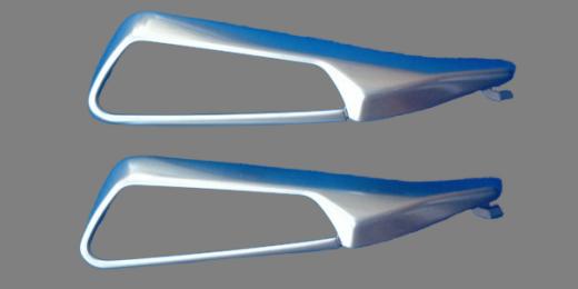

This technical study reviews archived simulation slides identified as left- and right-hand vertical-fin components. It uses the recorded analysis conditions to discuss filling and venting checkpoints; proposed checks below are not reported production actions.

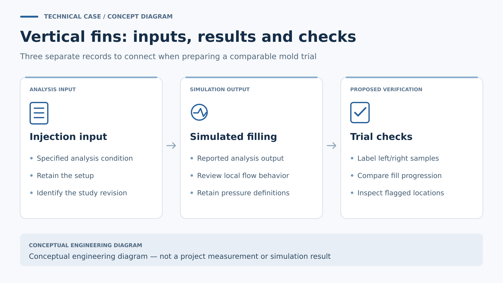
Separate the requested input from the reported fill
The archived study lists a mold-temperature input of 50°C, a melt-temperature input of 230°C and an injection-time input of 0.75 seconds. The reported simulation fill is approximately 0.77 seconds, with a pressure figure of 38.6 MPa. The slides also recommend attention to venting.
Keeping input and result separate matters. Their small numerical difference is an analysis observation, not a measured molding tolerance or proof of a repeatable production cycle. A reviewer would need the full setup and result definitions before explaining why the two times differ.
The component names identify the subject as vertical fins. Detailed conclusions about wall thickness, gate position or cavity arrangement still require the actual geometry and mold layout. None of those features should be reconstructed from a filename alone.
Look for local behavior within the short fill event
A short overall fill time can still contain regions that advance differently. For a fin-type component, the useful review is to follow the flow front through the actual geometry and identify where progression slows, where regions finish and where air may become enclosed.
If the drawing contains thin sections connected to thicker flow paths, hesitation deserves specific attention. Autodesk describes how flow can favor a less-resistant thick section while slowing in a thinner region; prolonged hesitation can allow that region to freeze before filling is complete. This is a general mechanism to investigate, not a defect established for these archived parts. Technical reference: Autodesk hesitation guidance.
An appropriate review would compare fill progression with temperature results where available. If a proposed gate or process change is evaluated, it should address an identified region and preserve a clear comparison with the original study.
Translate the venting note into accessible tooling features
The archived venting recommendation should prompt a review of the predicted final-filling and convergence regions. The next question is whether the actual mold design provides a usable air-release path at those locations.
For a comparable project, a vent proposal should identify both the cavity-side position and the route beyond it. It should also consider access for inspection and maintenance. A vent that can be located on a simulation image still needs a practical tool-design detail, with dimensions agreed for the resin and molding conditions.
The pressure figure belongs in the same review, with its result definition retained. It should not be treated as evidence that every local region fills adequately or as a prescribed pressure setting for a future machine.
Plan a trial that can test the prediction
A focused trial could use clearly labeled sample sets to compare observed filling progression with the selected simulation revision. Where safe and appropriate, a planned short-fill sequence can help reveal the order in which regions develop. The team should define that sequence and its recording method before the trial.
For the left- and right-hand components, identification should remain visible in both samples and records. Inspection can then concentrate on drawing-defined features and the locations flagged during analysis, including incomplete fill, visible flow marks or other specified surface conditions.
The useful output is a traceable comparison: a modeled observation, a trial condition and an actual sample observation. Any adjustment to vents, gate design or processing would then have a defined reason and a verification step.
Prepare a fin-component mold review
Provide the current part models, resin specification, required appearance, functional features and intended molding arrangement. Include existing analysis files when available. Contact GPTMOLD to discuss the scope, supported by the DFM review overview.